Rgz on technical mechanics solution. Basic laws and formulas in theoretical mechanics. Solving examples. Theorem on the change in the kinetic energy of a mechanical system
Many university students face certain difficulties when they begin to teach basic technical disciplines, such as strength of materials and theoretical mechanics, in their course of study. This article will consider one of these subjects - the so-called technical mechanics.
Technical mechanics is the science that studies various mechanisms, their synthesis and analysis. In practice, this means a combination of three disciplines - strength of materials, theoretical mechanics and machine parts. It is convenient in that each educational institution chooses in what proportion to teach these courses.
Accordingly, in most control works The tasks are divided into three blocks, which must be solved separately or together. Let's consider the most common tasks.
Section one. Theoretical mechanics
Of the variety of problems in theoretical mechanics, one can most often meet problems from the section of kinematics and statics. These are tasks on the balance of a flat frame, the definition of the laws of motion of bodies and the kinematic analysis of the lever mechanism.
To solve problems for the equilibrium of a flat frame, it is necessary to use the equilibrium equation for a flat system of forces:
![]()
The sum of the projections of all forces on the coordinate axes is equal to zero and the sum of the moments of all forces about any point is equal to zero. By solving these equations together, we determine the magnitude of the reactions of all supports of the flat frame.
In tasks for determining the main kinematic parameters of the movement of bodies, it is necessary, based on a given trajectory or the law of motion of a material point, to determine its speed, acceleration (full, tangential and normal) and the radius of curvature of the trajectory. The laws of point motion are given by the trajectory equations:
The projections of the point velocity on the coordinate axes are found by differentiating the corresponding equations:
![]()
By differentiating the velocity equations, we find the projections of the acceleration of the point. The tangential and normal accelerations, the radius of curvature of the trajectory are found graphically or analytically:
![]()
![]()
The kinematic analysis of the lever mechanism is carried out according to the following scheme:
- Partitioning the mechanism into Assur groups
- Construction for each of the groups of plans for speeds and accelerations
- Determination of speeds and accelerations of all links and points of the mechanism.
Section two. Strength of materials
The strength of materials is a section that is quite difficult to understand, with many different tasks, most of which are solved according to its own methodology. In order to make it easier for students to solve their problems, most often in the course of applied mechanics they are given elementary problems for the simple resistance of structures - moreover, the type and material of the structure, as a rule, depends on the profile of the university.
The most common problems are tension-compression, bending and torsion.
In tension-compression problems, it is necessary to construct diagrams of longitudinal forces and normal stresses, and sometimes also displacements of structural sections.
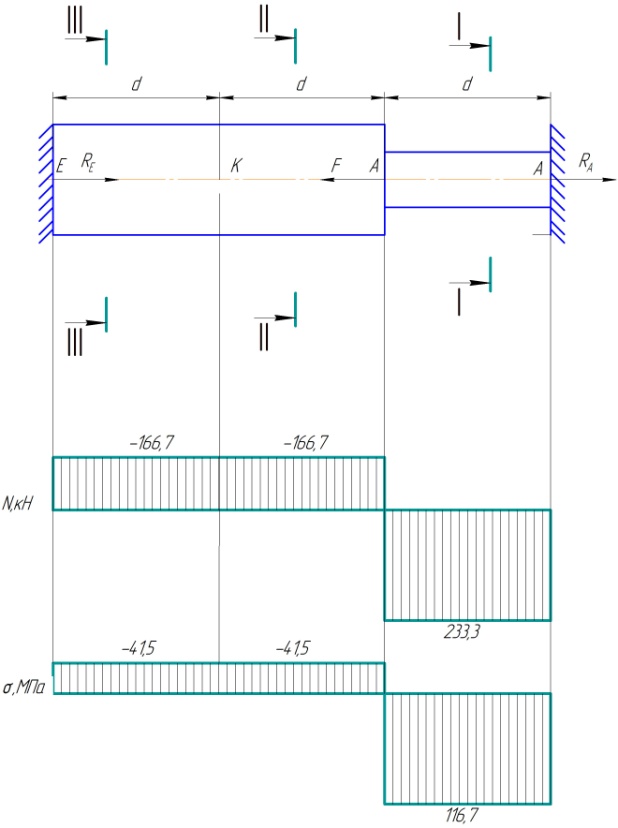
To do this, it is necessary to divide the structure into sections, the boundaries of which will be the places where the load is applied or the cross-sectional area changes. Further, applying the formulas for the equilibrium of a solid body, we determine the values of internal forces at the boundaries of the sections, and, taking into account the cross-sectional area, internal stresses.
According to the data obtained, we build graphs - diagrams, taking the axis of symmetry of the structure as the graph axis.
Torsion problems are similar to bending problems, except that instead of tensile forces, torques are applied to the body. With this in mind, it is necessary to repeat the calculation steps - partitioning into sections, determining the twisting moments and angles of twisting and plotting.
In bending problems, it is necessary to calculate and determine the transverse forces and bending moments for a loaded beam.
First, the reactions of the supports in which the beam is fixed are determined. To do this, you need to write down the equilibrium equations of the structure, taking into account all the acting forces.
After that, the beam is divided into sections, the boundaries of which will be the application points external forces. By considering the balance of each section separately, the transverse forces and bending moments at the boundaries of the sections are determined. Based on the data obtained, plots are built.
The cross-sectional strength test is carried out as follows:
- The location of the dangerous section is determined - the section where the greatest bending moments will act.
- From the condition of strength in bending, the moment of resistance of the cross section of the beam is determined.
- The characteristic section size is determined - diameter, side length or profile number.
Section three. Machine parts
The "Machine Details" section combines all the tasks for calculating mechanisms that work in real conditions - this can be a conveyor drive or a gear train. It greatly facilitates the task that all formulas and calculation methods are given in reference books, and the student only needs to choose those that are suitable for a given mechanism.
Literature
- Theoretical mechanics: Guidelines and control tasks for part-time students of engineering, construction, transport, instrument-making specialties of higher educational institutions/ Ed. prof. S.M.Targa, - M.: graduate School, 1989 Fourth edition;
- A. V. Darkov, G. S. Shpiro. "Strength of materials";
- Chernavsky S.A. Course design of machine parts: Proc. manual for students of mechanical engineering specialties of technical schools / S. A. Chernavsky, K. N. Bokov, I. M. Chernin, etc. - 2nd ed., revised. and additional - M. Mashinostroenie, 1988. - 416 p.: ill.
Solution of technical mechanics to order
Our company also offers services for solving problems and tests in mechanics. If you have difficulty understanding this subject, you can always order a detailed solution from us. We take on difficult tasks!
can be free.
Kinematics
Kinematics of a material point
Determining the speed and acceleration of a point from given equations her movements
Given: Equations of motion of a point: x = 12 sin(πt/6), cm; y= 6 cos 2 (πt/6), cm.
Set the type of its trajectory and for the moment of time t = 1 s find the position of a point on the trajectory, its velocity, full, tangential and normal accelerations, as well as the radius of curvature of the trajectory.
Translational and rotational motion of a rigid body

Given:
t = 2 s; r 1 = 2 cm, R 1 = 4 cm; r 2 = 6 cm, R 2 = 8 cm; r 3 \u003d 12 cm, R 3 \u003d 16 cm; s 5 \u003d t 3 - 6t (cm).
Determine at time t = 2 the velocities of points A, C; angular acceleration of wheel 3; point B acceleration and rack acceleration 4.
Kinematic analysis of a flat mechanism

Given:
R 1 , R 2 , L, AB, ω 1 .
Find: ω 2 .

The flat mechanism consists of rods 1, 2, 3, 4 and slider E. The rods are connected by means of cylindrical hinges. Point D is located in the middle of bar AB.
Given: ω 1 , ε 1 .
Find: speeds V A , V B , V D and V E ; angular velocities ω 2 , ω 3 and ω 4 ; acceleration a B ; angular acceleration ε AB of link AB; positions of instantaneous centers of speeds P 2 and P 3 of links 2 and 3 of the mechanism.
Determining the absolute speed and absolute acceleration of a point

A rectangular plate rotates around a fixed axis according to the law φ = 6 t 2 - 3 t 3. The positive direction of reading the angle φ is shown in the figures by an arc arrow. Rotation axis OO 1 lies in the plane of the plate (the plate rotates in space).
The point M moves along the straight line BD along the plate. The law of its relative motion is given, i.e., the dependence s = AM = 40(t - 2 t 3) - 40(s - in centimeters, t - in seconds). Distance b = 20 cm. In the figure, point M is shown in the position where s = AM > 0 (for s< 0 point M is on the other side of point A).
Find the absolute speed and absolute acceleration of point M at time t 1 = 1 s.
Dynamics
Integration of differential equations of motion of a material point under the action of variable forces
A load D of mass m, having received an initial velocity V 0 at point A, moves in a curved pipe ABC located in a vertical plane. On the section AB, the length of which is l, the load is affected by a constant force T (its direction is shown in the figure) and the force R of the resistance of the medium (the module of this force is R = μV 2, the vector R is directed opposite to the velocity V of the load).
The load, having completed its movement in section AB, at point B of the pipe, without changing the value of its velocity modulus, passes to section BC. On the section BC, a variable force F acts on the load, the projection F x of which on the x axis is given.
Considering the load as a material point, find the law of its motion on the section BC, i.e. x = f(t), where x = BD. Ignore the friction of the load on the pipe.

Download solution
Theorem on the change in the kinetic energy of a mechanical system
The mechanical system consists of weights 1 and 2, a cylindrical roller 3, two-stage pulleys 4 and 5. The bodies of the system are connected by threads wound on pulleys; sections of threads are parallel to the corresponding planes. The roller (solid homogeneous cylinder) rolls along the reference plane without slipping. The radii of the steps of pulleys 4 and 5 are respectively R 4 = 0.3 m, r 4 = 0.1 m, R 5 = 0.2 m, r 5 = 0.1 m. The mass of each pulley is considered uniformly distributed along its outer rim . The supporting planes of weights 1 and 2 are rough, the coefficient of sliding friction for each weight is f = 0.1.
Under the action of force F, the modulus of which changes according to the law F = F(s), where s is the displacement of the point of its application, the system begins to move from a state of rest. When the system moves, resistance forces act on the pulley 5, the moment of which relative to the axis of rotation is constant and equal to M 5 .
Determine the value of the angular velocity of pulley 4 at the moment when the displacement s of the point of application of force F becomes equal to s 1 = 1.2 m. 
Download solution
Application of the general equation of dynamics to the study of the motion of a mechanical system
For a mechanical system, determine the linear acceleration a 1 . Consider that for blocks and rollers the masses are distributed along the outer radius. Cables and belts are considered weightless and inextensible; there is no slippage. Ignore rolling and sliding friction. 
Download solution
Application of the d'Alembert principle to the determination of the reactions of the supports of a rotating body
Vertical shaft AK rotating uniformly with angular velocityω \u003d 10 s -1, fixed with a thrust bearing at point A and a cylindrical bearing at point D.
A weightless rod 1 with a length l 1 = 0.3 m is rigidly attached to the shaft, on free end which there is a load of mass m 1 = 4 kg, and a homogeneous rod 2 with a length of l 2 = 0.6 m, having a mass of m 2 = 8 kg. Both rods lie in the same vertical plane. The points of attachment of the rods to the shaft, as well as the angles α and β are indicated in the table. Dimensions AB=BD=DE=EK=b, where b = 0.4 m. Take the load as material point.
Neglecting the mass of the shaft, determine the reactions of the thrust bearing and the bearing.

Tasks for settlement-analytical and settlement-graphic works on all sections of the course of technical mechanics are given. Each task includes a description of the solution of problems with brief guidelines, examples of solutions are given. The applications contain the necessary reference material. For students of construction specialties of secondary vocational schools.
Determination of reactions of ideal bonds in an analytical way.
1. Indicate the point whose equilibrium is being considered. In tasks for independent work such a point is the center of gravity of the body or the point of intersection of all rods and threads.
2. Apply active forces to the considered point. In tasks for independent work, the active forces are the own weight of the body or the weight of the load, which are directed downward (more correctly, towards the center of gravity of the earth). In the presence of a block, the weight of the load acts on the considered point along the thread. The direction of this force is determined from the drawing. Body weight is usually denoted by the letter G.
3. Mentally discard connections, replacing their action with reactions of connections. In the proposed problems, three types of bonds are used - an ideally smooth plane, ideally rigid straight rods and ideally flexible threads - hereinafter referred to as a plane, a rod and a thread, respectively.
TABLE OF CONTENTS
Foreword
Section I. Independent and control work
Chapter 1. Theoretical mechanics. Statics
1.1. Analytical Determination of Ideal Bond Reactions
1.2. Determination of the support reactions of a beam on two supports under the action of vertical loads
1.3. Determination of the position of the center of gravity of the section
Chapter 2. Strength of materials
2.1. Selection of sections of rods based on strength
2.2. Determination of the main central moments of inertia of the section
2.3. Plotting Shear Forces and Bending Moments for a Simple Beam
2.4. Determination of the allowable value of the central compressive force
Chapter 3
3.1. Construction of diagrams of internal forces for the simplest single-circuit frame
3.2. Graphical determination of forces in truss rods by constructing a Maxwell-Cremona diagram
3.3. Determination of linear movements in the simplest cantilever frames
3.4. Calculation of a statically indeterminate (continuous) beam according to the equation of three moments
Section II. Settlement and graphic works
Chapter 4. Theoretical mechanics. Statics
4.1. Determination of forces in the rods of the simplest cantilever truss
4.2. Determination of support reactions of a beam on two supports
4.3. Determination of the position of the center of gravity of the section
Chapter 5
5.1. Determination of forces in bars of a statically indeterminate system
5.2. Determination of the main moments of inertia of the section
5.3. Selection of the section of a beam from a rolled I-beam
5.4. Selection of the section of the centrally compressed composite rack
Chapter 6
6.1. Determination of forces in sections of a three-hinged arch
6.2. Graphical determination of forces in the bars of a flat truss by constructing a Maxwell diagram - Cremona
6.3. Calculation of a statically indeterminate frame
6.4. Calculation of a continuous beam according to the equation of three moments
Applications
Bibliography.
Free download e-book in a convenient format, watch and read:
Download the book Collection of problems in technical mechanics, Setkov VI, 2003 - fileskachat.com, fast and free download.
Download pdf
Below you can buy this book at the best discounted price with delivery throughout Russia.


