Channels of connection. Classification of communication channels. Communication channels parameters. Condition for signal transmission over a communication channel
Control
Communication, communication, radio electronics and digital devices
Communication channel - a system of technical means and a signal propagation environment for transmitting messages (not just data) from a source to a recipient (and vice versa). A communication channel, understood in a narrow sense (communication path), represents only the physical medium of signal propagation, for example, a physical communication line.
Question number 3 “Communication channels. Classification of communication channels. Communication channels parameters. Condition for signal transmission over a communication channel.
Link
Link a system of technical means and a signal propagation environment for transmitting messages (not just data) from a source to a recipient (and vice versa). A communication channel understood in a narrow sense ( communication path ) represents only the physical propagation medium, such as a physical communication line.
The communication channel is designed to transmit signals between remote devices. The signals carry information intended for presentation to the user (human), or for use by computer application programs.
The communication channel includes the following components:
- transmitting device;
- receiving device;
- transmission medium of various physical nature (Fig.1) .
The information-carrying signal formed by the transmitter, after passing through the transmission medium, is fed to the input of the receiving device. Further, the information is extracted from the signal and transmitted to the consumer. The physical nature of the signal is chosen so that it can propagate through the transmission medium with minimal attenuation and distortion. The signal is needed as a carrier of information, it does not carry information itself.
Fig.1. Communication channel (option No. 1)
Fig.2 Communication channel (option No. 2)
Those. it is (channel) technical device (technology + environment).
Classification
There will be exactly three types of classifications. Choose your taste and color:
Classification #1:
There are many types of communication channels, among which the most common arewired channels connections ( air, cable, light guide etc.) and radio channels (tropospheric, satelliteand etc.). Such channels, in turn, are usually qualified on the basis of the characteristics of the input and output signals, as well as the change in the characteristics of the signals depending on such phenomena occurring in the channel as fading and attenuation of signals.
According to the type of distribution medium, communication channels are divided into:
- wired;
- acoustic;
- optical;
- infrared;
- radio channels.
Communication channels are also classified into:
- continuous (at the input and output of the channel continuous signals),
- discrete or digital (at the input and output of the channel discrete signals),
- continuous-discrete (at the channel inputcontinuous signals, and at the outputdiscrete signals),
- discrete-continuous (at the channel inputdiscrete signals, and at the outputcontinuous signals).
Channels can be linear and non-linear, time and spatio-temporal.
Possible classification of communication channels by frequency range.
Information transmission systems are single-channel and multi-channel . The system type is determined by the communication channel. If the communication system is built on the same type of communication channels, then its name is determined by the typical name of the channels. Otherwise, the specification of classification features is used.
Classification No. 2 (more detailed):
- Classification according to the frequency range used
- Kilometer (LW) 1-10 km, 30-300 kHz;
- Hectometer (SV) 100-1000 m, 300-3000 kHz;
- Decameter (HF) 10-100 m, 3-30 MHz;
- Meter (MV) 1-10 m, 30-300 MHz;
- Decimeter (UHF) 10-100 cm, 300-3000 MHz;
- Centimeter (SMW) 1-10 cm, 3-30 GHz;
- Millimeter (MMV) 1-10 mm, 30-300 GHz;
- Decimal (DMMV) 0.1-1 mm, 300-3000 GHz.
- According to the direction of communication lines
- directed ( different conductors are used):
- According to the direction of communication lines
- coaxial,
- twisted pairs based on copper conductors,
- fiber optic.
- non-directional (radio links);
- line of sight;
- tropospheric;
- ionospheric
- space;
- radio relay (retransmission on decimeter and shorter radio waves).
Type of messages sent:
- telegraph;
- telephone;
- data transmission;
- facsimile.
- Type of signals:
- analog;
- digital;
- impulse.
- By type of modulation (manipulation)
- In analog communication systems:
- By type of modulation (manipulation)
- with amplitude modulation;
- with single-sideband modulation;
- with frequency modulation.
- In digital communication systems:
- with amplitude manipulation;
- with frequency shift keying;
- with phase shift keying;
- with relative phase shift keying;
- with tone keying (single elements manipulate the subcarrier oscillation (tone), after which manipulation is carried out at a higher frequency).
- By the value of the radio signal base
- broadband (B>> 1);
- narrowband (B»1).
7. By the number of simultaneously transmitted messages
- single-channel;
- multichannel (frequency, time, code division of channels);
8.
By message direction
- unilateral;
- bilateral.
9. In order of message exchange - simplex communicationtwo-way radio communication, in which the transmission and reception of each radio station is carried out in turn;
- duplex communicationtransmission and reception are carried out simultaneously (the most efficient);
- half duplexrefers to simplex, which provides for automatic transition from transmission to reception and the possibility of asking the correspondent again.
10. By ways of protecting transmitted information
- open communication;
- closed communication (secret).
11. According to the degree of automation of information exchange
- manual radio control and messaging performed by the operator;
- automated only information is entered manually;
- automatic the process of exchanging messages is performed between an automatic device and a computer without the participation of an operator.
Classification No. 3 (something may be repeated):
1. By appointment
Telephone
Telegraph
TV
- broadcasting
2. By direction of transmission
- simplex (transmission in one direction only)
- half duplex (transmission alternately in both directions)
- duplex (transmit simultaneously in both directions)
3. By the nature of the line of communication
Mechanical
hydraulic
Acoustic
- electrical (wired)
- radio (wireless)
Optical
4. By the nature of the signals at the input and output of the communication channel
- analog (continuous)
- discrete in time
- discrete by signal level
- digital (discrete both in time and in level)
5. By the number of channels per communication line
single channel
Multichannel
And another drawing here:
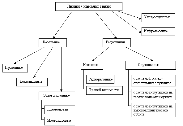
Fig.3. Classification of communication lines.
Characteristics (parameters) of communication channels
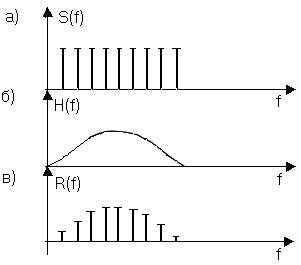
- Channel transfer function: presented in the formamplitude-frequency characteristic (AFC) and shows how the amplitude of the sinusoid at the output of the communication channel decays compared to the amplitude at its input for all possible frequencies of the transmitted signal. The normalized frequency response of the channel is shown in Fig.4. Knowing the frequency response of a real channel allows you to determine the shape of the output signal for almost any input signal. To do this, it is necessary to find the spectrum of the input signal, convert the amplitude of its constituent harmonics in accordance with the amplitude-frequency characteristic, and then find the shape of the output signal by adding the converted harmonics. For experimental verification of the amplitude-frequency characteristic, it is necessary to test the channel with reference (equal in amplitude) sinusoids over the entire frequency range from zero to some maximum value that can occur in the input signals. Moreover, you need to change the frequency of the input sinusoids with a small step, which means that the number of experiments should be large.
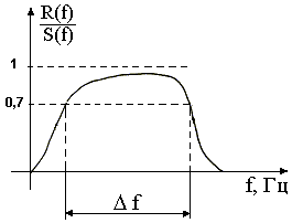
- ratio of the spectrum of the output signal to the input
bandwidth
Fig.4 Normalized frequency response of the channel
- Bandwidth: is a derivative characteristic of the frequency response. It is a continuous range of frequencies for which the ratio of the amplitude of the output signal to the input exceeds a certain predetermined limit, that is, the bandwidth determines the frequency range of the signal at which this signal is transmitted over the communication channel without significant distortion. Typically, the bandwidth is measured at 0.7 of the maximum frequency response. The bandwidth to the greatest extent affects the maximum possible speed of information transfer over the communication channel.
- Decay : is defined as the relative decrease in the amplitude or power of a signal when a signal of a certain frequency is transmitted over a channel. Often, during the operation of the channel, the fundamental frequency of the transmitted signal is known in advance, that is, the frequency whose harmonic has the highest amplitude and power. Therefore, it is sufficient to know the attenuation at this frequency in order to approximately estimate the distortion of the signals transmitted over the channel. More accurate estimates are possible if the attenuation at several frequencies corresponding to several fundamental harmonics of the transmitted signal is known.
Attenuation is usually measured in decibels (dB) and is calculated using the following formula:, where
signal power at the channel output,
signal power at the channel input.
The attenuation is always calculated for a specific frequency and is related to the channel length. In practice, the concept of "specific attenuation" is always used, i.e. signal attenuation per unit channel length, for example, attenuation of 0.1 dB/meter.
- Transmission speed: characterizes the number of bits transmitted over the channel per unit of time. It is measured in bits per second bps , as well as derived units:Kbps, Mbps, Gbps. The transmission rate depends on the channel bandwidth, noise level, coding type and modulation.
- Channel noise immunity: characterizes its ability to provide signal transmission under interference conditions. Interference is divided into internal (representsthermal noise of equipment) and external (they are varied anddepend on the transmission medium). The noise immunity of the channel depends on the hardware and algorithmic solutions for processing the received signal, which are embedded in the transceiver.Noise immunitysignaling through a channelcan be increased at the expense coding and special processing signal.
- Dynamic Range: the logarithm of the ratio of the maximum signal power transmitted by the channel to the minimum.
- Noise immunity:This is noise immunity.e. interference immunity.
The condition for signal transmission over communication channels.
The channel is essentially a filter. In order for the signal to pass through it without distortion, the volume of this channel must be greater than or equal to the signal (see Fig.).
Mathematically, the condition can be written as follows: , where
; (1)
In the above formulas
channel bandwidth, or the frequency band that the channel can miss with normalized signal attenuation;
dynamic range equal to the ratio of the maximum allowable signal level in the channel to the level of interference normalized for this type of channels;
time during which the channel is used for data transmission;
the width of the signal frequency spectrum, i.e. the interval on the frequency spectrum scale occupied by the signal;
dynamic range equal to the ratio of the average signal power to the average interference power in the channel;
the duration of the signal, or the time of its existence.
Another form of writing a condition (expanded):
P. S .: The parameter "Channel volume" in some sources is also indicated as one of the parameters of the communication channel, but not everywhere. The mathematical formula is given above in (1).
Literature
1. http://edu.dvgups.ru/METDOC/ENF/BGD/BGD_CHS/METOD/ANDREEV/WEBUMK/frame/1.htm;
2. http://supervideoman.narod.ru/index.htm.
As well as other works that may interest you |
|||
| 50472. | Social security in post-penitentiary institutions | 91.87KB | |
| Studying the problems of persons in respect of whom detention was chosen as a preventive measure, persons released from places of detention and conditions conducive to their return to normal social life, as well as studying the main aspects of social work with this category of citizens, as well as finding a way to ensure effective category data protection. | |||
| 50475. | Study of the propagation of light in an anisotropic medium and the interference of polarized rays. Determining the parameters of a quartz wedge | 773KB | |
| Interference of polarized light. The purpose of the work: to study the propagation of light in an anisotropic medium and the interference of polarized rays. When light passes through all transparent crystals of a non-cubic system, birefringence is observed. Even with normal incidence of light on the crystal, the extraordinary ray deviates from the normal. | |||
| 50476. | Creating a Remote InterBase Database | 1.35MB | |
| Create database table domains using domain integrity constraints. Create tables with referential integrity and entity constraint. Fill tables with data of at least 5 records. Create a trigger to change table values. | |||
| 50477. | Radioelectronics. Collection of laboratory works | 3.95MB | |
| The study of electronic voltage stabilizers Breakdown pn junction The phenomenon of a sharp increase in reverse current with a slight increase in reverse voltage above a certain value is called the breakdown pn junction. The avalanche breakdown is reversible after the voltage is reduced, the process stops and the current drops sharply. In the absence of external voltage, Fig. | |||
| 50478. | Ways to correct an image in Adobe Photoshop | 341.5KB | |
| The mechanism of action of the correction consists in the simultaneous transformation of all selected pixels into a new state. Of course, the most popular of the raster graphics editors, dobe Photoshop, provides a wide range of different correction tools. Different correction methods can eliminate various kinds of defects. | |||
| 50479. | PicoScope 2203 Digital Oscilloscope User Guide | 344.5KB | |
| The image capture panel contains keys and menus for controlling the waveform image: Oscilloscope mode Persistence mode Spectrum analyzer mode Automatic setting key automatically selects the parameters of the best waveform image Scope reset key restores the original settings of the oscilloscope Sweep factor selection menu determines the time per division Horizontal stretch menu allows scaling waveform in horizontal... | |||