3.8. Data transmission via digital communication channels
The principle of data transmission but digital communication channels will be considered using the example of the IKM-30 system
The transmission medium in PCM systems is a digital linear path (LT)), the structure of which is shown in Fig. 3.49. It includes the transmitting and receiving terminal equipment of the LT, sections of the communication line to the regenerators, to coordinate the structure of the digital signal with the LT, the transmitting and receiving parts of the terminal equipment include, respectively, an encoder (CLT)) and a decoder (DLT) of the linear path. When using cable communication lines, digital signals are transmitted in the base frequency band using line coding. The location of the regenerator and the processing of the digital signal in it are chosen so as to provide the required noise immunity while minimizing the cost of creating a digital path. Data transmission can be carried out for a variety of purposes. Whether it is streaming video, downloading databases, video surveillance over the Internet, telephone conversations, both in circuit-switched mode and using Internet technologies. For all these applications, the channel remains approximately the same. Unless for a video signal it will be much wider than for text transmission.
The task of the transmitting part of the terminal equipment is the sampling of analog speech signals, the temporary combination of the received samples, their quantization; and coding. At the output of the quantizer, the signal has the same structure as the data signal. Therefore, it is possible to combine telephone messages and data. At the receiving end, inverse conversions are performed (signal decoupling, sampling recovery from a linear code, and their digital-to-analogue conversion).
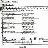
Time multiplexing of signals in PCM systems requires tight synchronization of transmitting and receiving equipment. For this, synchronization of the generators of the receiving station is provided for by the clock frequency, cycles and supercycles of the digital molasses. Clock synchronization ensures equality of signal processing speed at end stations. The transmission cycle of the group digital signal consists of timeslots (CI), clock signals (SS), control and interaction signals (SUV), auxiliary signals and data signals. The structure of the PCM group signal, shown in Fig. 3.50, includes 32 CIs, and its clock frequency J- is determined by the sampling frequency of speech signals fg = 8 kHz, the number of codeword bits for representing samples n = log2256=8 and the number of channels Nk = 32. For IKM-30 ft= 8-8-32 = 2048 kHz.
Digital synchronization ensures the correct distribution of code symbols in the CI, agreed with the transmitting side. The clock signal is located at the beginning of the cycle and its structure is such that it is easily detected on the receiving side (Fig. 3.50a). In PCM-30, the code synchrogroup has the form 0011011, it explores with a frequency of 4 kHz (in the CI of odd cycles).
Synchronization of the system for distributing control signals and interaction between switching nodes is ensured by the formation of multiframe synchronization (SCS), the code groups of which have the structure 0000 and will be transmitted every 16 cycles in the 17th CI, that is, with a repetition interval of 126 μx16 = 2 ms (Fig. 3 .50b). To ensure the operation of the transmission system, service symbols marked X, U, V are included in the structure of the cycle and supercycle, and in Fig. 3.50a. The letters a, b, c, d mean the symbols of the four signal channels assigned to the corresponding channel.
Therefore, the PCM-30 system, like any other digital system, allows a combined mode of use for the transmission of analog and discrete information (voice messages and data messages). It is possible to occupy part (or all) of the CI with data signals.

The advent of digital channels in communication systems made it possible to eliminate the need for the implementation of an expensive process of modulation and demodulation of binary signals in APD. The terminal equipment of digital channelization systems allows input of digital signals into the transmission system without conversion. This significant advantage of digital systems has allowed integration based on different types of communication. However, it should be remembered that the equipment of digital systems (first of all, systems with PCM with delta modulation DM and their varieties was created for the transmission of speech (analogue) signals, which determined the technical solutions of this equipment, in particular, the choice of sampling rate and the number of elements of code combinations. When transmitting data, it is not so much the level of the transmitted signal that matters, but the accuracy of determining its significant moments (transition from state "1" to state "0" or vice versa). The parameters of the digital system in which data transmission channels are organized determine their qualitative characteristics. Code combinations obtained as a result of the conversion of data transmission signals differ from the code combinations of analog telephone signals both in the number of symbols in the code combinations and in the sampling frequency.Usually, the duration of the shortest pulse (signal) of the data transmission is required to be greater than the strobe (sampling) period of the input signal. Principle p transmission of digital signals, including data signals, by transmitting information about the moment of change in the meaningful state of the digital signal and the directions of its change, allows you to organize "transparent" data transmission systems, i.e. systems that do not impose requirements on the code used for data signals, on their modulation rate and synchronization method
The input and transmission of data signals through the terminal devices of digital channeling systems can be carried out in two ways: by direct gating of data signals and transmission of information about the significant positions of these signals (simple overlay) or by identifying the moments of changes in significant positions and transmitting encoded information about them
Simple overlay method
In this method, data signals are input to the channel inputs of the terminal devices of digital systems and gated by a sequence of gate pulses. The resulting signal, consisting of sequences of strobe pulses corresponding to the state I of the binary signal, is introduced into the linear path. In the receiving equipment, the transmitted signal is reconstructed from the envelope of the received pulse sequence. The pulse shape of the transmitted, strobe, linear and received signals is shown in Fig. 3.51. With this transmission method, the strobe pulses are not synchronized with the data signal. This causes the transmission of significant modulation moments to occur with an error that is less than the strobe repetition period Te. The degree of edge distortion is equal to
![]()
where To is the duration of a single element of the data signal.
To ensure a high transmission probability (reducing edge distortion) in a system with a simple superposition, it is necessary to increase the repetition rate of the gate pulses.

The required gating frequency can be determined for a given value of Te and an expected amount of edge distortion. In the case of data transmission with a low modulation rate, this frequency is much lower than the 8 kHz sampling frequency used in PCM transmission systems. Therefore, to fully utilize the capacity of a digital channel, several low-frequency data transmission channels can be formed in it. The number of such channels can be defined as
![]()
where f. - frequency of strobing (sampling) of the digital system;
N is the modulation rate of the data signal;
§„ - coefficient of permissible distortion of the data signal.
When registering the received signals, an error in the binary signal appears only when the moment of erroneous reception of a pulse from the digital path falls into the middle of a single signal element yes4:-1x. Error multiplication factor eL = I.” if the number of errors in the binary signal is To/To times less than the number of errors in the digital path. Note that the simple overlay method is not suitable for data transmission systems with a high modulation rate due to the low degree of use of the digital channel bandwidth. For example, with a strobe frequency of 64 kHz and edge distortion of 2%, the degree of utilization of the digital channel is only 2.%. Therefore, this method is used for data transmission over digital channels only at a transmission rate of up to 1200 bps.
Moving index method.
This principle is based on the principle of code transmission of information about the presence of a transition in the data signal and its position in the time interval between the following clock pulses. This information is contained in code combinations consisting of i > 3 elements. The first element of the code combination carries information about the presence or absence of changes in the significant position of the binary signal, the next or subsequent zr-ment * about the direction of this change, the rest. -2 elements determine the position of the moment of change of the significant positions of the binary signal in relation to the clock pulses of the reading. The process of forming code combinations is presented in Figure 3.52.
Edge distortion with this method of data transmission for digital channels is 2 times less than with the simple overlay method at the same sampling frequency and data signal transmission rate. The number of the subinterval in which the transition is observed in the data signal is transmitted in binary code. The beginning of the transfer of the number is determined by the starting element, which is always a "one" (impulse 5 in Fig. 3.52). The position of this pulse is not synchronized with the pulse train of the digital path. This causes the starting pulse to slip along the time axis. hence the name of the sliding index method

In the event of a single error (false pulse) in the digital path, the receiving equipment can interpret it as the start pulse of the next code combination. False reception of the data signal will continue until the next code combination arrives, returning the agreement of the received and transmitted states, which is represented in Fig. 3.52 by the shaded area of the received signal. This is because there are more errors in the received binary signal than single false pulses in the digital path.
The propagation of errors inherent in this method can be avoided by combining the gliding pulse method with the simple overlay method, which is used to confirm the significant positions of the data signal. With this modification of the transmission method, the strobe pulses are fed into the digital path then. when the data signal element is an "I" state.
The appearance of a transition in the data signal causes the first element at the output of the encoder to take on a value (state) opposite to that of the preceding element. It also plays the role of the starting pulse of the code combination, which determines the moment of state change in relation to the sequence of the digital path (reading). In this case, the utilization rate of the digital path is higher than with the confirmation run method, due to the binary information contained in one element about the presence of the transition and its direction.
Fixed index method
This method differs from those described above in the principle of transmitting information about the significant moments of the data signal and the direction of the change in the polarity of the pulses at fixed times. The fixed reference pulse repetition rates mean that this method does not require the use of starting elements in certain codewords. However, the disadvantage of the method is the limitation of the channel capacity compared to the sliding index method when using the same number of code pulses.
Merging streams (grouping)
The task of digital multiplexing is to temporarily combine several digital signals received from different sources into a single digital signal (stream) with a correspondingly higher transmission rate. On transmission, it is necessary to combine signals from several sources, and on reception, the division of a group digital signal (stream) into components of each subchannel.
The principle of digital grouping can be understood from Fig. 3.53. A number of digital signals with the same transmission rate and a certain phase are fed to the input of the switch (distributor), which represents the corresponding time interval for each input signal. At the output of the switch, a composite signal Y is formed, which consists of a set of input signals. If an analog switch is switched on at the other end of the path, operating in phase (matched) with the transmitting one, then the composite signal can be again divided into the original signals. This method of generating a composite signal is called symbol interleaving. This term means that symbols of consecutive input signals are located side by side in a composite signal. Obviously, digital multiplexing with alternating channel time slots or alternating cycles is also possible. Compared to the other two, the character interleaving method has the following advantages:
- the memory capacity that needs to be used for each input signal is much (on the order of a few characters) less;
- information symbols of low-rate signals are evenly spaced in the cycle of the higher-order system. Here, a disruption in any of the lower-order systems does not prevent transmission of the remaining low-rate signals;
- the cycle structure of a higher-order system is independent of the cycle structure of lower-order systems;
- decorrelation of errors in code combination elements;
- symbol interleaving ensures uniform distribution of information symbols also in case of underutilization of higher-order system bandwidth
In practice, the signals to be combined have both different speeds and variable phases. The speed difference is a consequence of the fact that the different transmission systems are controlled by independent master oscillators; in addition, fluctuations in the transmission rate occur due to the phase jitter caused by the linear path.
Phase changes can be of three types: constant drift due to a constant frequency difference, short-term phase fluctuations and long-term (daily, seasonal) phase changes caused by changes in propagation time in transmission lines due to temperature changes.

In order for the digital multiplexing process to be carried out without errors and information loss, the digital multiplexing equipment must ensure the synchronization of the digital signals to be combined. Next, we briefly consider two digital multiplexing methods used in practice that allow achieving synchronism of the combined signals: synchronous digital multiplexing and asynchronous digital multiplexing by the digital equalization method (stuffing method).
The main feature of synchronous digital multiplexing is the use of only one master oscillator, the frequency of which corresponds to the speed of the combined signal of the multiplexing equipment. Synchronization signals for the equipment of lower-order systems are obtained from this generator. A block diagram of a system for synchronously combining four lower-order input digital signals with a clock frequency f, into a single higher-order output digital stream with a clock frequency f^ is shown in Fig. 3.54. The dependence of the distance between the frequencies f, and 4< имеет следующий вид:
![]()
where f is the redundancy of the cycle or the ratio of the number of additional symbols in the cycle to the number of information symbols.

Synchronization from the master oscillator occurs as follows. The main master oscillator located in the digital multiplexing equipment B controls the operation of the transmitting part of the equipment. The higher order digital signal is transmitted over a line path to the digital multiplexing equipment C, where a synchronization signal is allocated for the receiving and transmitting parts. The synchronization signal for the receiving part of the digital multiplexing equipment B is extracted from the information coming from the equipment C. In addition, in the transmitting parts of the digital multiplexing equipment B and C, the synchronization signal of the lower-order transmission systems is extracted, which serves to highlight the information of these systems. From the information transmitted to a specific set of equipment of the lowest order (a), Ad, Dt, D,), a clock signal with a frequency is extracted, which controls the operation of the transmitting and receiving parts of this equipment. Information from four sets of equipment A1 and four sets D is transmitted at a clock frequency, respectively, to digital grouping equipment B and C, in which this information should be read at a frequency taken as a reference. It should be noted that all four low-order digital signals entering equipment B or C have the same bit rate (clock frequency), while the phases of individual signals may differ and may change over time. Taking into account the phase changes of the signal, appropriate buffer memory devices must be used at the input of the grouping equipment B and C. The memory capacity must beat the maximum changes in signal propagation time. This implies the main drawback of synchronous digital multiplexing - the memory capacity must increase with the length of communication lines, and at a certain capacity, the length of the line must be limited. Hence, as a consequence, there is also a drawback, namely: inflexibility and limited possibilities for using such equipment on the network.
It is more widely used in practice by grouping using the digital alignment method / stuffing method).
Digital equalization is a method of bringing the changing speed of the combined digital signal to some reference speed, which in this case is the speed of the higher-order system in terms of one lower-order digital signal. Alignment is carried out by introducing additional outputs (aligning symbols) into the digital signal, or removing information symbols, the values of which are transmitted to the receiving device using an additional service channel. In order for the receiver to be able to restore the original digital signal in its original form, information about any operation carried out in the transmitter is sent to the receiver, in which the reverse operation is carried out. There are three types of digital equalization: positive, negative, and bilateral.
Positive equalization assumes that the sum of the maximum rates of the input signals to be combined is less than the rate of the composite signal. The input signals pass through timing devices that determine how much to speed them up to keep them in sync with the higher-order system signal. The input signal is padded with a certain number of characters. Information about additional characters is transmitted to the receiving station, where these characters will be omitted as redundant. There is a certain place in the cycle of a higher order system where an equalization pulse can be located, so it is enough to send information to the receiving side of the line that a digital equalization has taken place.
With negative digital equalization, it is assumed that the recording frequency in the memory device of the transmitting equipment f1 is greater than the reading frequency f2. In this regard, the memory will be filled until it overflows, however, before this happens, the threshold control circuit will delay the recording for a time equal to the duration of one character. Information that a symbol has been deleted, as well as its value, is transmitted over the service channel to. receiving side. The receiver extracts this information and delays reading from the memory receiver by a time equal to the duration of one character (which was removed at the transmitter). Due to the lack of advantages, negative equalization is not used as an independent method of digital grouping, since it is implemented using more complex devices.
In practice, (positive-negative) two-way digital equalization is of great interest. Here, if the input signal speed is less than nominal, then this signal is transmitted with positive equalization, if more than nominal, with negative equalization. The advantage of this alignment is its versatility, i.e. the possibility of synchronous and asynchronous operation with the same cycle structure. An example is the equipment of the digital transmission system "Impulse".
This equipment uses serial combining (disconnection) on a cyclic basis of single channel elements (nine synchronous-asynchronous "digital channels with a speed of 4.8 kbps, one digital channel with a speed" of 2.4 kbps, one "transparent" telegraph channel up to 100 bits.
test questions
1. How to explain the fact that with an increase in the data transfer rate over PM channels, the probability of an error increases if special protection measures are not taken?
2. Draw a timing diagram of the data signal in the PM channel at baud rates of 1200 and 2400 bps and frequency modulation.
3. What is the ratio between the frequencies of the carrier and modulating oscillations in modems
4. Point out the similarities and differences between FM and PM signals.
5. Prove that for small modulation indices, the width of the signal spectrum is almost equal to twice the upper modulation frequency
6. Draw oscillograms and spectra of pulses that satisfy the first Nyquist criterion.
7. Why is ORP signal demodulation so sensitive to timing quality?
8. Draw an amplitude-phase diagram for KAM-32 AFM-Z2
9. What is the relationship between specific bit rate and log2m value
10. Plot the amplitude-vector diagram for TOFM at various jitter swings.
11. Select modulation methods for data transmission over the PM channel with data bit rates of 4.8; 9.6 and 16 kbps.
12. Compare the influence of the characteristics of the PM channels on the RPK signals of the type of Fig. 3.12 and the type of Fig. 3.47 at the same data bit rate.